For my Ph.D. thesis work I’ve been working with a lot of linear systems theory. Because of my mathematics background, I typically think of linear systems details from a functional/harmonic analysis perspective, with real numbers, mostly continuous functions, etc. In the engineering world, however, we use discrete versions of these mathematics.
Motivation
The application which I’m applying linear systems to is a channel design for a channeled polarimeter. Abstractly we may think of channels in the typical communications sense, sets of $\delta$-functions in the Fourier domain which are convolved with the data (carrier channels/frequencies). The Fourier domain data around each channel can then be filtered out and deconvolved to obtain the spatio-temporal domain data for different channels.
In our polarimetric system design, we must temporally sample (via our focal plane array, i.e., a camera). We also are forced to use a window of samples, since we don’t have infinite time or computer memory. These windows must be integer periods of our carrier (or modulation) frequencies, otherwise we get spectral leakage. The seminal paper on spectral leakage and mitigating it is by Harris (1978). Basically when performing a discrete Fourier transform (DFT, including FFT), if the window is not an integer multiple of the period, then frequencies from the sharp cutoff become introduced into the DFT.
The issues
The camera on our polarimeter has a maximum framerate of 30 frames per second (fps). The bandwidth optimal system design (found so far) for this particular type of system has sets of 9 temporal channels (there are also spatial channels, and the channels are actually three dimensional spatio-temporal channels, but for simplicity here we may ignore this complexity), including the DC or 0 channel, corresponding to the temporal modulation dimension. Due to Hermicity, this means there are really 4 unique temporal frequencies other than 0 for this design, and they are evenly spaced. The maximum frequency is limited by the physical rotation speed limitations of a retarder, and the sample rate of the camera (due to Nyquist).
The above puts constraints on the windows, frequencies, and sampling rates that we can use without spectral leakage. It is sometimes theoretically desirable (for noise reasons in this polarimetric instrument) to sample at slightly above Nyquist, however in our case spectral leakage does not allow this. Our window must be an integer number of periods of all 4 frequencies. Practically this means that I cannot increase the sampling rate to something like 32 fps, because of the interplay between Nyquist, spectral leakage, and channel frequency spacing.
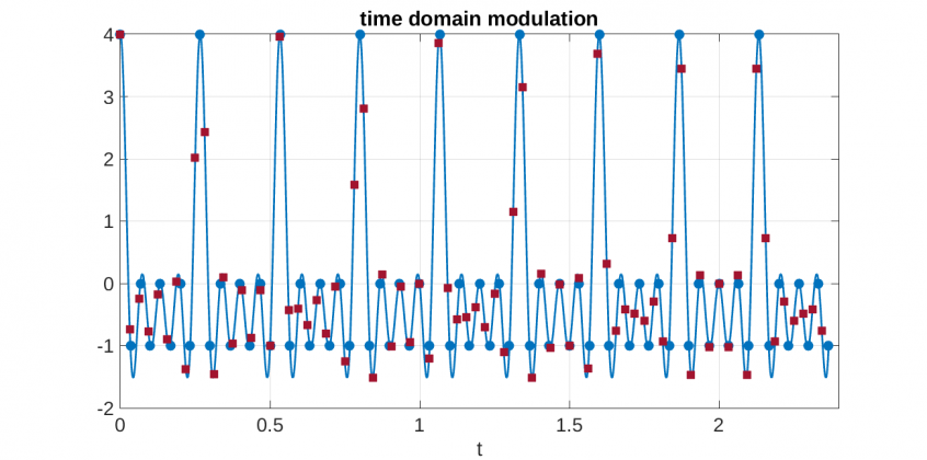
Below is a graph of $$ f(t) = \cos 2\pi(3.75t) + \cos2\pi(7.5t) + \cos2\pi(11.25t) + \cos2\pi(15t),$$ the blue dots denote sampling at 30 fps (or once every $\frac{1}{30}s$), and the red squares denote sampling at 32 fps.
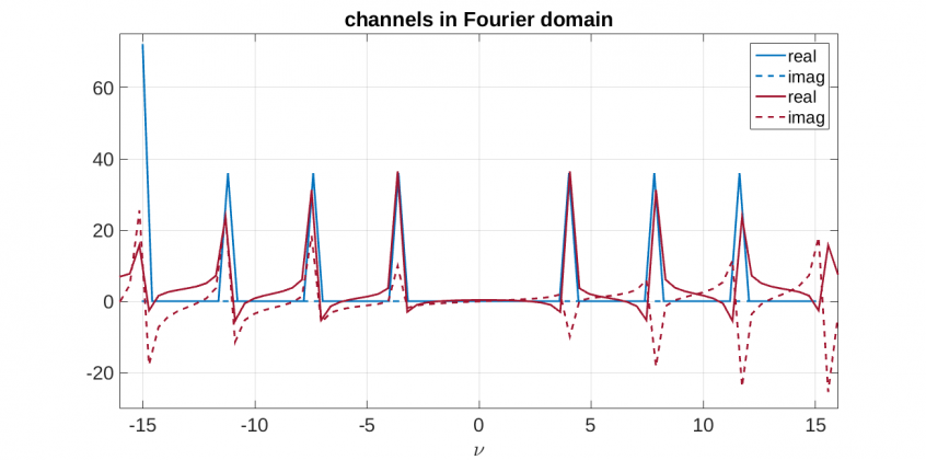
 When we take the Fourier transform (I use the unitary version here) $$\mathcal{F}\{f(t)\}_{t \to \nu}$$ for the 30fps sampled case we obtain the graph in blue below. This is the correct representation, there is no imaginary part, and the discrete $\delta$-functions are located precisely at the frequencies expected from the corresponding real (non-discrete) Fourier transform results. The red graphs show the spectral leakage issue, the imaginary part becomes non-zero, and the $\delta$-functions sort of “split” into positive and negative parts. This creates problems when trying to reconstruct data after filtering. Note that we have the leftmost $\delta$-function at twice the magnitude of the others, and a missing $\delta$-function on the right side, this is due to the channel being right at Nyquist.
 In the next post I will go over precisely what the mathematical relationship is between spectral leakage, Nyquist, and channel frequency, and the constraints imposed upon us as engineers when using channeled systems.

Leave a Reply